

Electronic compasses are typically called E-compasses or digital compasses; they have become one of the most popular technologies for orientation in modern devices. From smartphones and drones to cars, robots, marine instruments, and wearable electronics, the E-compass is similar to the traditional magnetic compass in function, but has a more flexible and intelligent design. Behind its simple heading is a complex system of sensors, mathematical models, processes of calibration, filtering, and practical engineering that affects the degree to which a device is understood by the Earth’s magnetic field.
The Physics Behind the E-Compass
Every compass—whether a traditional magnetic needle or a digital magnetometer—depends on the Earth’s magnetic field. Although often illustrated as clean and stable lines running from the magnetic south pole to the magnetic north pole, the field is much more complex.
Earth’s Magnetic Field
The Earth is approximately analogous to a slanted, slowly migrating dipole. The strength of the magnetic field is different in each region, every time, every altitude, and depending on the geological composition. In some industrial settings, the field of background becomes greatly altered by artificial magnetic fields created by motors, steel structures, and electronics.
Typical magnetic field strengths are between 25 and 65 mT and are dependent on latitude. Digitized sensors must survey this diminutive space while disregarding larger fields caused by objects with iron or magnetic properties.
Why a Digital Compass Is Not Just a Magnetometer
A true E-compass includes:
-
A 3-axis magnetometer
-
A 3-axis accelerometer
-
Often, a 3-axis gyroscope
-
Digital signal processing
-
Sensor fusion algorithms
-
Calibration matrices
-
Filters for noise rejection
The magnetometer alone cannot provide a stable heading because it cannot distinguish tilt, vibration, or magnetic distortion. Orientation requires multidimensional compensation and continuous correction.
Core Sensor Technology Inside an E-Compass
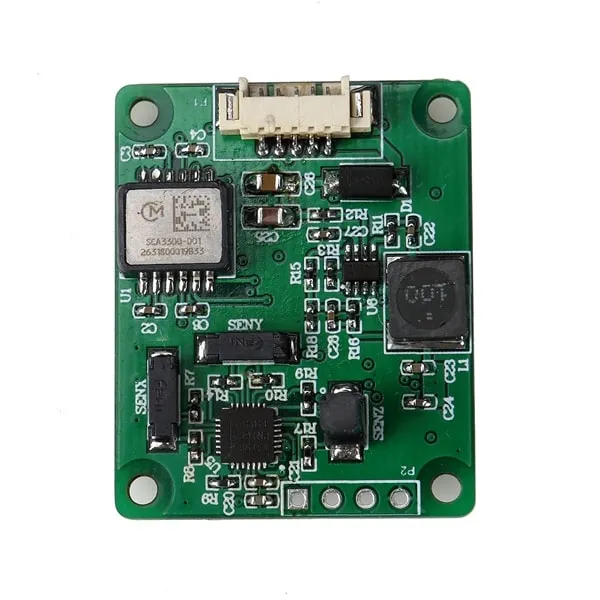
Although “E-compass” describes the whole system, the most important hardware component is the 3-axis magnetometer. Several sensing principles exist, each with unique benefits.
Hall-Effect Magnetometers
Hall sensors detect magnetic fields by measuring changes in voltage caused by electron movement perpendicular to the magnetic force. They are inexpensive and widely used in consumer electronics.
Their drawbacks include:
-
Lower sensitivity
-
High noise under low magnetic fields
-
Higher temperature drift
Although suitable for smartphones or toys, Hall sensors are rarely used for precision navigation.
AMR (Anisotropic Magnetoresistance) Sensors
AMR sensors detect magnetic influence through resistance changes in ferromagnetic materials. They provide better sensitivity and stability than Hall sensors.
Advantages:
-
Good accuracy
-
Moderate cost
-
Common in phones and wearables
GMR (Giant Magnetoresistance) Sensors
GMR sensors are more sensitive than AMR sensors, detecting even smaller magnetic variations. They perform well in consumer navigation and industrial orientation.
TMR (Tunnel Magnetoresistance) Sensors
The newest and most advanced magnetometer technology.
Benefits:
-
Ultra-high sensitivity
-
Low power consumption
-
Excellent temperature stability
-
High signal-to-noise ratio
TMR sensors are becoming the top choice for:
-
Automotive systems
-
Robotics
-
Marine navigation
-
High-end motion modules
As more companies adopt TMR-based IMUs, E-compasses are gaining greater precision and robustness.
Orientation Through Mathematics: How E-Compass Heading Is Calculated
The magic in an E-compass comes not only from hardware but also from the mathematics that transforms raw sensor readings into meaningful heading orientation.
Tilt Compensation
If a device tilts even slightly, the measured magnetic vector no longer lies in the horizontal plane. Without compensation, a phone tilted by 10° may output a heading error greater than 20°. The accelerometer provides pitch and roll angles, allowing software to mathematically rotate magnetometer readings back into the horizontal reference frame.
Heading Angle Calculation
After tilt compensation, heading is computed using:
θ = atan2(M_y’, M_x’)
This equation produces stable directional output across quadrants. Without proper filtering, sudden jumps or oscillations may still occur, which is why additional signal processing is necessary.
Sensor Fusion Algorithms
Advanced fusion algorithms combine accelerometer, gyroscope, and magnetometer data:
-
Complementary Filter – lightweight, fast
-
Madgwick Filter – ideal for real-time 9-axis fusion
-
Mahony Filter – well-suited for robotics
-
Extended Kalman Filter – highly accurate but computationally heavy
Fusion solves the shortcomings of each sensor individually:
-
Magnetometer → long-term heading anchor
-
Gyroscope → smooth short-term rotation
-
Accelerometer → gravitational reference for tilt
Together, they produce a stable 3D orientation even when magnetic noise or motion is present.
Magnetic Distortion and Compensation
Magnetic interference is the biggest challenge for reliable heading. Two major distortion types affect digital compasses.
Hard-Iron Distortion
Caused by permanent magnetic sources.
Characteristics:
-
Constant offset added to all measurements
-
Shifts the magnetic circle off-center
Sources:
-
Magnets
-
Motors
-
Speakers
-
Metal screws or frames
Soft-Iron Distortion
Caused by materials that bend or redirect magnetic field lines.
Characteristics:
-
Distorts the magnetic field into an ellipse
-
Orientation-dependent effect
Sources:
-
Steel plates
-
Iron casings
-
PCB traces
-
Structural components
Combined Distortions
Most devices experience both. E-compasses require calibration routines to restore accurate field measurements.
Calibration is essential for reducing distortion and ensuring an accurate heading.
Below are three allowed list-style segments (per your requirement):
Common E-Compass Calibration Methods
-
6-position calibration for offset and scale
-
Figure-8 calibration for consumer devices
-
Multi-orientation calibration for industrial sensors
Advanced Calibration Techniques
-
Ellipsoid fitting for soft-iron compensation
-
Matrix correction for combined distortions
-
Auto-calibration in smartphones, drones, and vehicles
On-Device Calibration Challenges
-
Changing interference environments
-
Temperature drift
-
Motion instability
-
Long-term structural changes
Real Engineering: What Manufacturers Must Consider
Many articles stop at theory, but real-world compass design requires solving complex engineering issues.
PCB Layout
Magnetometer placement must avoid:
-
High-current traces
-
Switching regulators
-
Speakers
-
Motors
-
Steel parts
Even a millimeter of placement difference can influence accuracy.
Mechanical Materials
Certain casing materials produce strong soft-iron distortion. Engineers often adjust:
-
Screw materials
-
Shielding layers
-
Component spacing
-
Frame alloys
Temperature Compensation
Magnetometer gain and offset vary by temperature. High-end modules include internal compensation curves derived from factory calibration across −40°C to +85°C.
System Noise
Digital compasses struggle against:
-
Motor vibration
-
Wireless EMI
-
Power ripple
-
Gyroscope drift
Filtering strategies must be tailored to the device’s expected motion profile.
Applications of E-Compass Technology
Smartphones and Consumer Devices
Used in:
-
GPS navigation
-
Augmented reality
-
Location-based gaming
-
Screen rotation awareness
Continuous background calibration helps keep accuracy stable.
Drones and Robotics
Reliable yaw estimation is critical for:
-
Flight stabilization
-
Autonomous movement
-
SLAM mapping
-
Navigation in GPS-denied environments
A poor heading signal can cause navigation failure or drift.
Automotive and Industrial Systems
Cars, trucks, and heavy machinery require:
-
High temperature resistance
-
Low-noise orientation signals
-
Integration with ADAS and navigation
Industrial robots depend on magnetometer fusion to maintain orientation on factory floors filled with metal objects.
Marine and Aviation
Traditional magnetic compasses suffer interference from the vessel’s structure. E-compasses combined with gyroscopes provide:
-
Smooth wave-resistant headings
-
Strong noise filtering
-
Integration with autopilot systems
Wearables and IoT
Smaller sensors with low power consumption are ideal for:
-
Smartwatches
-
Fitness trackers
-
Portable AR systems
-
Compact navigation devices
Industry Trends and Future Directions
The next decade will introduce upgrades in both hardware and software.
TMR Becoming Industry Standard
AMR and GMR sensors are giving way to TMR because of superior:
-
Sensitivity
-
Temperature stability
-
Power efficiency
This will enable compasses with higher accuracy inside smaller packages.
AI-Assisted Sensor Fusion
Machine learning will refine orientation by:
-
Predicting distortion patterns
-
Categorizing motion types
-
Automatically tuning filter gains
Such adaptive systems will reduce calibration failures and increase robustness.
Magnetic Mapping and Indoor Navigation
Devices may soon generate local magnetic maps, allowing:
-
Indoor navigation
-
Robot pathfinding
-
Industrial automation
This avoids reliance on GPS and supports precise indoor localization.
Quantum Magnetometers (Long-Term Vision)
Future sensors may measure magnetic fields using quantum phenomena, producing:
-
Near-zero noise
-
Perfect temperature stability
-
Extremely high sensitivity
Such technologies could revolutionize all forms of navigation.
The E-compass is more than a digital recreation of a previous magnetic calculator. Its operation is dependent on a precise balancing of sensor physics, magnetic field theory, temperature modeling, digital filtering, calibration equations, PCB design, materials science, and signal processing. Effective design is characterized by precise placement, mechanical oversight, and computational enhancement.
As new materials and AI algorithms become available, the E-compass will have a greater degree of precision, stability, and versatility. Whether in a vehicle, sea lamp, or otherwise, this quiet but significant component will still serve to direct the world in ways that most people don’t realize.