


Abstract
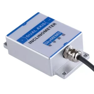
An electronic inclinometer sensor is a precision instrument designed to measure the angle at which an object is tilted or inclined relative to gravity. Modern inclinometer sensors use microelectromechanical systems (MEMS) technology, accelerometers, or gyroscope integration to convert angular displacement into an electrical signal.
According to Sensors and Actuators A: Physical (2022) and IEEE Transactions on Instrumentation and Measurement (2021), they operate by detecting gravitational acceleration components along multiple axes and computing tilt angles using trigonometric algorithms.
These sensors are widely used in robotics, construction, automotive systems, aerospace, and industrial automation to ensure accurate alignment, safety, and performance monitoring. For engineers and system integrators implementing precision orientation control, understanding their step-by-step operation is crucial.
Referenced Literature / Sources:
- Sensors and Actuators A: Physical, 2022 – MEMS-Based Inclinometer Principles
- IEEE Transactions on Instrumentation and Measurement, 2021 – High-Accuracy Tilt Sensor Applications
- National Instruments Technical Guide on Sensor Integration
Introduction to Electronic Inclinometer Sensors
Electronic inclinometer sensors, also known as tilt sensors or electronic levels, measure the angular displacement of an object in one or more axes relative to a reference plane — usually the gravitational vertical. Unlike mechanical inclinometers, which rely on pendulums or bubble levels, electronic inclinometers convert motion into electrical signals. This offers higher precision, digital interfacing, and robust performance in dynamic environments.
They are widely used in:
- Civil engineering: monitoring structures, slopes, or bridges
- Robotics: orientation feedback and stabilisation
- Aerospace: attitude monitoring
- Automotive systems: vehicle roll and pitch sensing
- Industrial automation: machinery alignment and safety
Core Principles of an Electronic Inclinometer Sensor
At its core, an electronic inclinometer sensor detects tilt by measuring the components of gravitational acceleration. When the sensor is inclined, the gravitational vector is projected onto its sensitive axes. The sensor measures these projections and converts them into voltage, current, or digital signals. The device then uses trigonometric functions to calculate the angle, typically via onboard microcontrollers or digital signal processors.
Key operating principles include:
- Gravitational sensing: Measuring acceleration due to gravity along one or more axes.
- Signal conversion: Translating physical tilt into a measurable electrical output.
- Angle computation: Using arctangent or trigonometric algorithms to determine inclination angles.
- Output delivery: Providing analogue voltage or current, or digital communication signals (I2C, SPI, or RS485).
Step-by-Step Working of an Electronic Inclinometer Sensor
Below is a detailed, step-by-step guide to how an electronic inclinometer sensor functions:
Step 1: Sensor initialisation
When powered on, the inclinometer sensor calibrates its internal electronics to zero inclination based on the current reference plane. For MEMS-based sensors, this may involve:
- Establishing baseline accelerometer offsets;
- Temperature compensation for bias drift;
- Activating internal filters to reduce noise.
This ensures that subsequent measurements are accurate and stable.
Step 2: Detection of Gravitational Components
The sensor contains microstructures or accelerometers aligned along one or more axes. As the device tilts:
- The gravitational vector decomposes into X, Y, and Z components relative to the sensor axes.
- MEMS capacitive elements detect the displacement caused by the tilt.
- Changes in capacitance or resistance correspond to acceleration components along each axis.
Step 3: Conversion to Electrical Signal
The sensor converts physical tilt into electrical signals using:
- Capacitive sensing (MEMS): Measures the displacement of microstructures
- Resistive sensing (strain gauges): Detects bending or deflection
- Piezoelectric sensing: Generates voltage under mechanical strain.
The result is an analogue voltage or current that is proportional to the tilt magnitude.
Step 4: Signal conditioning
Raw sensor signals are typically small and noisy. Signal conditioning includes:
- Amplification (increasing the signal amplitude);
- Filtering (reducing noise and interference);
- Linearisation (correcting the non-linear sensor response).
This step is critical for reliable digital conversion.
Step 5: Optional analogue-to-digital conversion
Many modern sensors include built-in ADCs that convert conditioned analogue signals into digital data. Digital outputs simplify integration with:
- Microcontrollers
- PLCs (programmable logic controllers)
- Embedded control systems
Step 6: Analog-to-digital conversion (optional)
Many modern sensors include built-in ADCs that convert conditioned analogue signals into digital data.
Digital outputs simplify integration with:
- Microcontrollers
- PLCs (programmable logic controllers)
- Embedded control systems
Step 7: Angle computation
The sensor calculates tilt angles using trigonometry:
- Single-axis sensor: θ = arcsin(Ax/g)
- Dual-axis sensor: θ_x = arctan(Ax/Az), θ_y = arctan(Ay/Az)
Where Ax, Ay, and Az are the measured acceleration components, and g is the standard gravitational acceleration. Multi-axis sensors may use vector mathematics or complementary filters to estimate angles with high precision.
Step 8: Data Output
The sensor finally delivers the computed tilt angles in the following ways:
- Analog signals (0–5 V, 4–20 mA)
- Digital communication (I2C, SPI, RS485, CAN bus)
- Wireless protocols (Bluetooth, Wi-Fi for smart applications)
Users or control systems can then read the real-time tilt data for monitoring or feedback control purposes.
Advantages of Electronic Inclinometer Sensors
Electronic inclinometer sensors, also known as tilt or digital inclinometers, are widely used in industrial, automotive, and robotics applications to accurately measure angles of tilt or slope. These sensors offer several key advantages over traditional mechanical inclinometers.
- High precision and accuracy
Capable of detecting minute angular changes, often in fractions of a degree, making them suitable for applications requiring tight tolerances and exact positioning. Digital output ensures consistent readings with minimal drift.
- Compact and lightweight design
- Small form factor allows integration into space-constrained systems
- Lightweight construction reduces the load on mechanical structures
- -Ideal for mobile platforms, drones, and robotic arms
- Fast response time
- Electronic sensors provide real-time tilt measurement
- Enable dynamic control in automated systems
- Support high-speed operations, such as in industrial machinery and vehicle stabilisation
- Durability and reliability
- No moving parts reduce mechanical wear and tear
- Resistant to shock, vibration, and environmental stress
- Long operational lifespan under harsh conditions
- Easy integration and data output
- Can interface with microcontrollers, PLCs, and data acquisition systems
- Provides analogue or digital signals compatible with modern control systems
- Facilitates monitoring, logging, and remote control
- Multi-axis measurement
Some models measure two or three axes simultaneously, enabling more complex orientation tracking and spatial analysis. This is useful in robotics, construction, and navigation systems.
Applications Across Industries
| Industry | Application | Sensor Type |
| Construction | Bridge tilt monitoring | MEMS inclinometer |
| Automotive | Vehicle stability control | Gyro-integrated tilt sensor |
| Robotics | Robot arm orientation | Digital inclinometer |
| Aerospace | Aircraft attitude | Multi-axis inclinometer |
| Industrial Automation | Machinery alignment | Analog/digital inclinometer |
Key Factors Affecting Sensor Accuracy
The performance of electronic inclinometer sensors is affected by several environmental, mechanical, and electrical factors.
- Sensor calibration
- Proper calibration is essential for precise angular measurement.
- Factory calibration may need adjusting for specific operational conditions.
- Drift over time requires periodic recalibration.
- Environmental conditions
- Temperature variations can affect sensor output and stability.
- Humidity, dust, or corrosive environments may degrade performance.
- Using sensors with temperature compensation and sealed housings improves reliability.
- Mounting and alignment
Misalignment or improper mounting can introduce systematic errors. Ensure the sensor is firmly fixed and aligned with the reference axes. Avoid mechanical vibrations that can affect readings.
- Electrical noise and interference
Electromagnetic interference (EMI) can cause signal distortion. Use shielded cables and proper grounding to maintain accuracy. A stable power supply ensures consistent sensor performance.
- Sensor resolution and range
- Higher-resolution sensors provide finer measurement detail.
- Using a sensor outside its optimal measurement range reduces accuracy.
- Select a sensor suited to the expected tilt angles.
Maintenance and Calibration
To ensure the long-term accuracy, reliability, and performance of electronic inclinometer sensors, proper maintenance and regular calibration are essential. Failing to do so can result in measurement drift, operational errors, and reduced system efficiency.
- Regular maintenance practices:
Inspect the physical condition:
- Check for visible damage, corrosion, or wear on the sensor housing and mounting.
- Inspect cables and connectors for fraying, loose connections, or damaged insulation.
- Ensure the sensor is securely mounted and free from vibration or misalignment.
Keep the sensor clean:
- Remove dust, dirt, and debris using soft, lint-free cloths or compressed air.
- Avoid using harsh chemicals that can damage the sensor housing or seals.
- Clean connectors and terminals to maintain stable electrical contact.
Environmental protection:
- Ensure that the sensors are operating within the specified temperature and humidity ranges.
- Use protective enclosures or seals in harsh or outdoor environments.
- Avoid prolonged exposure to direct sunlight, water ingress, or corrosive chemicals.
Monitor sensor performance:
- Regularly compare sensor readings to known reference angles.
- Watch for unexpected drift or inconsistent readings.
- Document performance trends to anticipate maintenance needs.
- Calibration guidelines
Calibration ensures that the sensor provides accurate angular measurements over its operational range.
Factory vs. field calibration:
Factory calibration is performed before shipment to provide a baseline level of accuracy.
Field calibration may be necessary in the following cases:
- New installations
- After mechanical shock or extreme environmental exposure
- Periodic maintenance cycles
Step-by-step field calibration:
- Prepare the reference surface. Use a precision flat or angular reference surface.
- Level the sensor. Align the sensor according to the manufacturer’s guidelines.
- Record baseline readings. Compare the sensor output with the known reference angles.
- Adjust the offset/scale. Apply calibration adjustments using software or hardware controls.
- Verify accuracy. Test across the full tilt range to ensure a linear response.
Frequency of calibration:
- Industrial applications: every 6–12 months or after major mechanical impacts
- Critical processes: more frequent verification, potentially monthly
- Keep calibration logs for quality control and traceability.
- Best practices for longevity
- Avoid operating the sensor beyond the specified tilt or temperature limits.
- Reduce mechanical shocks by using vibration-damping mounts.
- Use shielded cables to prevent electrical interference.
- Combine regular maintenance and calibration schedules to prevent drift.
FAQ: Electronic Inclinometer Sensor
Q1: What is an electronic inclinometer sensor?
A: It is a sensor that measures tilt or inclination relative to gravity, converting physical movement into an electrical signal.
Q2: How accurate are electronic inclinometer sensors?
A: Accuracy ranges from ±0.1° for high-end MEMS sensors to ±1° for low-cost units, depending on calibration and environment.
Q3: Can these sensors measure multiple axes?
A: Yes, dual- and tri-axis sensors measure pitch, roll, and sometimes yaw angles.
Q4: What are common outputs from these sensors?
A: Analog voltage/current, I2C, SPI, RS485, CANbus, and in some smart sensors, Bluetooth/Wi-Fi.
Q5: How do MEMS-based inclinometers work?
A: MEMS devices use microstructures whose capacitance changes under tilt, then convert this to a voltage proportional to the angle.
Q6: Where are electronic inclinometers used?
A: In robotics, automotive systems, aerospace, construction, industrial automation, and smart devices.
Conclusion
Electronic inclinometer sensors provide precise and reliable tilt measurements in real time across multiple industries. These sensors convert gravitational acceleration into electrical signals, process the data through signal conditioning and digital computation, and output tilt angles for monitoring or control.
They have therefore replaced mechanical levels in most modern applications. It is essential for engineers, technicians, and system integrators designing automated systems, vehicle stability controls, or structural monitoring solutions to understand the step-by-step operation of electronic inclinometer sensors.